预估到手价是按参与促销活动、以最优惠的购买方案计算出的价格(不含优惠券部分),仅供参考,未必等同于实际到手价。
-
>
中医基础理论
-
>
高校军事课教程
-
>
毛泽东思想和中国特色社会主义理论体系概论(2021年版)
-
>
中医内科学·全国中医药行业高等教育“十四五”规划教材
-
>
中医诊断学--新世纪第五版
-
>
中药学·全国中医药行业高等教育“十四五”规划教材
-
>
中医外科学——全国中医药行业高等教育“十四五”规划教材
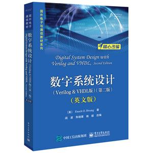
数字系统设计:Verilog & VHDL版:英文版 版权信息
- ISBN:9787121334214
- 条形码:9787121334214 ; 978-7-121-33421-4
- 装帧:一般胶版纸
- 册数:暂无
- 重量:暂无
- 所属分类:>>
数字系统设计:Verilog & VHDL版:英文版 本书特色
随着微电子技术与计算机技术的飞速发展,以及先进的电子设计自动化(EDA)技术及现场可编程门阵列(FPGA)器件的广泛应用,现代数字逻辑电路与系统的设计理念及实现技术已经发生了翻天覆地的变化。本书以微处理器系统作为复杂数字逻辑系统的代表,在简要介绍其工作原理的基础上,以CPU硬件结构框图为线索贯穿各个章节,详细讲述了如何构建基本组合/时序逻辑元件、如何利用已有元件组建数据通路与控制单元部件、如何利用已有部件实现一个通用CPU,以及如何通过进一步添加简单的输入输出接口来*终搭建出一个完整的微处理器系统。本书通过在简单的数字逻辑元件与复杂的实用数字逻辑系统之间搭建桥梁,能够帮助读者深刻理解数字逻辑组件的设计与使用方法,进而全面和清晰地把握复杂数字系统的EDA设计与实现技术要点。本书及相关网站提供了丰富的实用学习资源,所有设计示例都提供了电路图以及Verilog与VHDL源码。
数字系统设计:Verilog & VHDL版:英文版 内容简介
本书通过在简单的数字逻辑元件与复杂的实用数字逻辑系统之间搭建桥梁,能够帮助读者深刻理解数字逻辑组件的设计与使用方法,进而全面和清晰地把握复杂数字系统的EDA设计与实现技术要点。本书及相关网站提供了丰富的实用学习资源,所有设计示例都提供了电路图以及Verilog与VHDL源码。
数字系统设计:Verilog & VHDL版:英文版 目录
1.1 Overview of Microprocessor Design
1.2 Design Abstraction Levels
1.3 Examples of a 2-to-1 Multiplexer
1.3.1 Behavioral Level
1.3.2 Gate Level
1.3.3 Transistor Level
1.4 Introduction to Hardware Description Language
1.5 Synthesis
1.6 Going Forward
1.7 Problems
Chapter 2 Fundamentals of Digital Circuits
2.1 Binary Numbers
2.1.1 Counting in Binary
2.1.2 Converting between Binary and Decimal
2.1.3 Octal and Hexadecimal Notations
2.1.4 Binary Number Arithmetic
2.2 Negative Numbers
2.2.1 Two’s Complement Representation
2.2.2 Sign Extension
2.2.3 Signed Number Arithmetic
2.3 Binary Switch
2.4 Basic Logic Operators and Logic Expressions
2.5 Logic Gates
2.6 Truth Tables
2.7 Boolean Algebra and Boolean Equations
2.7.1 Boolean Algebra
2.7.2 Duality Principle
2.7.3 Boolean Functions and Their Inverses
2.8 Minterms and Maxterms
2.8.1 Minterms
2.8.2 Maxterms
2.9 Canonical, Standard, and Non-Standard Forms
2.10 Digital Circuits
2.11 Designing a Car Security System
2.12 Verilog and VHDL Code for Digital Circuits
2.12.1 Verilog Code for a Boolean Function
2.12.2 VHDL Code for a Boolean Function
2.13 Problems
Chapter 3 Combinational Circuits 65
3.1 Analysis of Combinational Circuits
3.1.1 Using a Truth Table
3.1.2 Using a Boolean Function
3.2 Synthesis of Combinational Circuits
3.2.1 Using Only NAND Gates
3.3 Minimization of Combinational Circuits
3.3.1 Boolean Algebra
3.3.2 Karnaugh Maps
3.3.3 Don’t-Cares
3.3.4 Tabulation Method
3.4 Timing Hazards and Glitches
3.4.1 Using Glitches
3.5 BCD to 7-Segment Decoder
3.6 Verilog and VHDL Code for Combinational Circuits
3.6.1 Structural Verilog Code
3.6.2 Structural VHDL Code
3.6.3 Dataflow Verilog Code
3.6.4 Dataflow VHDL Code
3.6.5 Behavioral Verilog Code
3.6.6 Behavioral VHDL Code
3.7 Problems
Chapter 4 Standard Combinational Components
4.1 Signal Naming Conventions
4.2 Multiplexer
4.3 Adder
4.3.1 Full Adder
4.3.2 Ripple-Carry Adder
4.3.3 Carry-Lookahead Adder
4.4 Subtractor
4.5 Adder-Subtractor Combination
4.6 Arithmetic Logic Unit
4.7 Decoder
4.8 Tri-State Buffer
4.9 Comparator
4.10 Shifter
4.11 Multiplier
4.12 Problems
Chapter 5 Sequential Circuits
5.1 Bistable Element
5.2 SR Latch
5.3 Car Security System—Version 2
5.4 SR Latch with Enable
5.5 D Latch
5.6 D Latch with Enable
5.7 Verilog and VHDL Code for Memory Elements
5.7.1 VHDL Code for a D Latch with Enable
5.7.2 Verilog Code for a D Latch with Enable
5.8 Clock
5.9 D Flip-Flop
5.9.1 Alternative Smaller Circuit
5.10 D Flip-Flop with Enable
5.10.1 Asynchronous Inputs
5.11 Description of a Flip-Flop
5.11.1 Characteristic Table
5.11.2 Characteristic Equation
5.11.3 State Diagram
5.12 Register
5.13 Register File
5.14 Memories
5.14.1 ROM
5.14.2 RAM
5.15 Shift Registers
5.15.1 Serial-to-Parallel Shift Register
5.15.2 Serial-to-Parallel and Parallel-to-Serial Shift Register
5.15.3 Linear Feedback Shift Register
5.16 Counters
5.16.1 Binary Up Counter
5.16.2 Binary Up Counter with Parallel Load
5.17 Timing Issues
5.18 Problems
Chapter 6 Finite-State Machines
6.1 Finite-State Machine Models
6.2 State Diagrams
6.3 Analysis of Finite-State Machines
6.3.1 Next-State Equations
6.3.2 Next-State Table
6.3.3 Output Equations
6.3.4 Output Table
6.3.5 State Diagram
6.3.6 Example
6.4 Synthesis of Finite-State Machines
6.4.1 State Diagram
6.4.2 Next-State Table
6.4.3 Next-State Equations
6.4.4 Output Table and Output Equations
6.4.5 FSM Circuit
6.5 Optimizations for FSMs
6.5.1 State Reduction
6.5.2 State Encoding
6.5.3 Unused States
6.6 FSM Construction Examples
6.6.1 Car Security System—Version 3
6.6.2 Modulo-6 Up-Counter
6.6.3 One-Shot Circuit
6.6.4 Simple Microprocessor Control Unit
6.6.5 Elevator Controller Using a Moore FSM
6.6.6 Elevator Controller Using a Mealy FSM
6.7 Verilog and VHDL Code for FSM Circuits
6.7.1 Behavioral Verilog Code for a Moore FSM
6.7.2 Behavioral Verilog Code for a Mealy FSM
6.7.3 Behavioral VHDL Code for a Moore FSM
6.7.4 Behavioral VHDL Code for a Mealy FSM
6.8 Problems
Chapter 7 Dedicated Microprocessors
7.1 Need for a Datapath
7.2 Constructing the Datapath
7.2.1 Selecting Registers
7.2.2 Selecting Functional Units
7.2.3 Data Transfer Methods
7.2.4 Generating Status Signals
7.3 Constructing the Control Unit
7.3.1 Deriving the Control Signals
7.3.2 Deriving the State Diagram
7.3.3 Timing Issues
7.3.4 Deriving the FSM Circuit
7.4 Constructing the Complete Microprocessor
7.5 Dedicated Microprocessor Construction Examples
7.5.1 Greatest Common Divisor
7.5.2 High-Low Number Guessing Game
7.5.3 Traffic Light Controller
7.6 Verilog and VHDL Code for Dedicated Microprocessors
7.6.1 FSM1D Model
7.6.2 FSMD Model
7.6.3 Algorithmic Model
7.7 Problems
Chapter 8 General-Purpose Microprocessors
8.1 Overview of the CPU Design
8.2 The EC-1 General-Purpose Microprocessor
8.2.1 Instruction Set
8.2.2 Datapath
8.2.3 Control Unit
8.2.4 Complete Circuit
8.2.5 Sample Program
8.2.6 Simulation
8.2.7 Hardware Implementation
8.3 The EC-2 General-Purpose Microprocessor
8.3.1 Instruction Set
8.3.2 Datapath
8.3.3 Control Unit
8.3.4 Complete Circuit
8.3.5 Sample Program
8.3.6 Hardware Implementation
8.4 Extending the EC-2 Instruction Set
Chapter 9 Interfacing Microprocessors
9.1 Multiplexing 7-Segment LED Display
9.1.1 Theory of Operation
9.1.2 Controller Design
9.2 Issues with Interfacing Switches
9.3 3×4 Keypad Controller
9.3.1 Theory of Operation
9.3.2 Controller Design
数字系统设计:Verilog & VHDL版:英文版 作者简介
Enoch O. Hwang 于美国加州大学Riverside分校获计算机科学博士学位,目前是南加州Sierra大学计算机科学系助理教授,加州大学Riverside分校电子工程系、计算机科学与工程系讲师,主要讲授数字逻辑设计课程。
Enoch O. Hwang 于美国加州大学Riverside分校获计算机科学博士学位,目前是南加州Sierra大学计算机科学系助理教授,加州大学Riverside分校电子工程系、计算机科学与工程系讲师,主要讲授数字逻辑设计课程。
- >
巴金-再思录
巴金-再思录
¥33.1¥46.0 - >
小考拉的故事-套装共3册
小考拉的故事-套装共3册
¥36.7¥68.0 - >
月亮虎
月亮虎
¥15.4¥48.0 - >
人文阅读与收藏·良友文学丛书:一天的工作
人文阅读与收藏·良友文学丛书:一天的工作
¥27.3¥45.8 - >
有舍有得是人生
有舍有得是人生
¥21.2¥45.0 - >
姑妈的宝刀
姑妈的宝刀
¥11.4¥30.0 - >
回忆爱玛侬
回忆爱玛侬
¥10.5¥32.8 - >
名家带你读鲁迅:故事新编
名家带你读鲁迅:故事新编
¥13.0¥26.0
-
家居设计解剖书
¥27.3¥39 -
网络安全基础
¥27.7¥39.5 -
家具造型设计
¥34.3¥49 -
工程硕士研究生英语基础教程学生用书
¥45.6¥68 -
国外电子与通信教材系列信号与系统(第二版)
¥69.3¥99 -
工程机械维修
¥30.8¥40


